Introduction to Catchment Hydraulics and
Open Channel Flow (CIVL3140) Introduction to Catchment Hydraulics and
Open Channel Flow (CIVL3140)
Introduction to Catchment Hydraulics and
Open Channel Flow (CIVL3140) Introduction to Catchment Hydraulics and
Open Channel Flow (CIVL3140)Catchment hydraulics. Behaviour of flows in channels; open channel flow; uniform equilibrium and gradually-varied flows; hydraulic modelling; culvert design.
Subject purpose: The aim of the subject is to develop a sound understanding of the fundamental fluid mechanics principles and their application to professional water engineering problems. Fundamental fluid mechanics principles are applied to professional water engineering problems. As a result of undertaking the subject, each student will comprehend the hydraulics of rivers and canals, and grasp the basic catchment processes.Subject rationale: The term 'Hydraulics' is related to the application of the Fluid Mechanics principles to water engineering structures, civil and environmental engineering facilities: e.g., canal, river, dam, reservoir, water treatment plant.In the subject, the students are introduced to the hydraulics of a catchment : rainfall, runoff and streamflow. The section "Introduction to Open channel flows" applies the basic principles of fluid mechanics to open channel flows. Examples of open channels are natural streams and rivers. Man-made channels include irrigation and navigation canals, drainage ditches, sewer and culvert pipes running partially full, and spillways. The lecture draws upon the students' expertise in catchment hydrology and water runoff gained in Hydrology Part of the subject. The teaching is focused on the application of the fundamental principles to open channel flow. The interactions between hydrology and hydraulics (e.g. rainfall and river discharge) are further discussed and the students are introduced to real-world engineering situations including failures. At the end of the subject, the design of a hydraulic system is introduced based on a system approach. The hydraulic structure must be analysed as part of the surrounding catchment and the hydrology plays an important role. Structural and hydraulic constraints interact, and the design of a hydraulic structure is a complex exercise altogether. First the system must be identified. What are the design objectives ? What are the constraints ? What is the range of options ? What is the "best choice" ? Its detailed analysis must be conducted and the engineers should ask : is this solution really satisfactory ? During design stages, physical and computational models may be reliable 'tools' to compare the performances of various design options.After completion of the subject, each student will know how to apply the fundamental fluid mechanics principles to professional designs and they will be familiar with the multi-disciplinary aspects of an engineering project.
Assumed background: The subject is a professional subject. It is expected that the students have mastered the fundamental principles of fluid mechanics (subject CIVL3130). The subject is the first of a series of two subjects (CIVL3140 and CIVL4120) dealing with river engineering, hydraulic structures and their interactions with the environment.
The subject outline file may be downloaded : Click here (Word format) [Version 29/07/02].Timetable : Click there (Excel format) [Version 1]
+ CHANSON, H. (1999). "The Hydraulics of Open Channel Flows : An Introduction." Butterworth-Heinemann, Oxford, UK, 512 pages (ISBN 0 340 74067 1). {Support website : http://www.bh.com/companions/0340740671} Corrections & Updates [Newsletters No. 1, No. 2]
Spanish edition : "Hidraulica Del Flujo De Canales Abiertos", McGraw Hill Interamericana, División Universidad, Columbia (ISBN: 958-410-256-7).
Chinese edition : Hydrology Bureau of Yellow River Conservancy Committee, March 2003 (ISBN 7-80621-529-8).
Review : "Without a doubt, this is the best introduction to the hydraulics of open channel flow that I have yet to read." Professor S.N. LANE, University of Leeds, Environmental Conservation, Volume 27 2000, Issue 3, pp 314-315. {Read Full Review}+ APELT, C.J. (1983). Hydraulics of Minimum Energy Culverts and Bridge Waterways, Australian Civil Engrg Trans., I.E.Aust., Vol. CE25, No. 2, pp. 89-95.+ CHANSON, H. (2000). Introducing Originality and Innovation in Engineering Teaching: the Hydraulic Design of Culverts, European Journal of Engineering Education, Vol. 25, No. 4, pp. 377-391.
+ CHANSON, H. (2001). "Teaching Hydraulic Design in an Australian Undergraduate Civil Engineering Curriculum." Jl of Hyd. Engrg., ASCE, Vol. 127, No. 12, pp. 1002-1008.
+ Environmental Hydraulics, CIVL4120 website
+ Environmental Modelling, CIVL4140 website
+ Softwares : HydroChan & HydroCulv by Hydrotools software (For teaching purposes only)

3. Froude Number
The Froude number is
proportional to the square root of the ratio of the inertial forces over the
weight of fluid. The Froude number is used generally for scaling free surface
flows, open channels and hydraulic structures. Although the dimensionless number
was named after William FROUDE, several French researchers used it before.
DUPUIT (1848) and BRESSE (1860) highlighted the significance of the number to
differentiate the open channel flow regimes. BAZIN (1865a) confirmed
experimentally the findings. Ferdinand REECH introduced the dimensionless number
for testing ships and propellers in 1852. The number is called the Reech-Froude
number in France (CHANSON 1999, pp.
39-46).
In rectangular channels, the Froude number is
commonly defined as the ratio of the flow velocity to the square root of the
product of g times d, where d is the flow depth and g is the gravity
acceleration.
4. Properties of Common Open-Channel Shapes
In
practice, natural and man-made channels do not have often a rectangular
cross-section. Critical flow conditions are defined as the flow conditions for
which the mean specific energy is minimum (CHANSON
1999, pp. 46-48). In a horizontal channel and assuming hydrostatic pressure
distribution, critical flow conditions imply :
Applications of the Momentum Principle : Hydraulic Jump, Surge, Flow
Resistance in Open Channels
2. Hydraulic jump
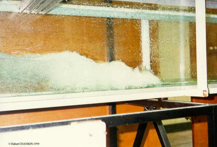
A hydraulic jump is a stationary transition from a rapid
(supercritical flow) to a slow flow motion (subcritical flow). Although the
hydraulic jump was described by LEONARDO DA VINCI, the first experimental
investigations were published by Giorgio BIDONE in 1820. It is extremely
turbulent and characterised by the development of large-scale turbulence,
surface waves and spray, energy dissipation and air entrainment (eg CHANSON and BRATTBERG
2000). The large-scale turbulence region is usually called the 'roller'.
Experimental observations highlight different types of hydraulic jumps,
depending upon the Froude number of the upstream flow. An undular hydraulic jump
is observed at low Froude numbers (1< Fr <3): looking downstream (Fr=1.2) and sideview
(Fr=1.6). With
increasing Froude numbers, other types of jumps include weak jump, oscillating
jump (3.5< Fr <4.5), steady jump and
strong jump
(Fr >10).
These photographs show surfers riding on a
hydraulic jump roller in a river in Munich, Germany (Photo No. 1 :
flow from right to left, Photo No. 2:
looking downstream, Courtesy of Dale YOUNG).
3. Surges and Tidal Bores
A
surge in an open channel is a sudden change of flow depth (i.e. abrupt increase
or decrease in depth). An abrupt increase in flow depth is called a positive
surge while a sudden decrease in depth is termed a negative surge. This picture
shows an undular
surge (propagation from left to right).
A positive
surge looks like a moving hydraulic jump. The application of the momentum
principle to the unsteady flow is based upon a quasi-steady flow situation
analogy (CHANSON
1999, pp. 67-71).
A bore is a positive surge of tidal
origin. Tidal bores occur as the tidal flow turns to rising (e.g. Lynch 1982)
(Links : (1) ). Famous ones
include the Hangchow (or Hangzhou) bore on the Qiantang
river (photo: (1),
(2) , (3) ), the Amazon bore
called pororoca (photo: (1), (2) , (3)
; info: see below ), the tidal bore on the Seine river (mascaret) (photo:
(1) ; info: (2) ), the Hoogly (or
Hooghly) bore on the Gange, the bore on the Mekong river. Smaller tidal bores
occur on the Severn river near Gloucester, England (photo : (1), (2) , (3) ), on the Trent river
(aegir) (photo: (1)), on the Garonne
and Dordogne rivers, France (photo: (1), (2) ,
(3); info: (3) ), at
Turnagain Arm and Knik Arm, Cook Inlet (Alaska) (info: (1) ; photo: (2) , (3) ), the
bores in the Bay of Fundy (New Brunswick, Nova Scotia) like at Petitcodiac
(info: (1)
), tidal bores on the Styx river QLD and on the Daly river NT (Australia), the
tidal bore called benak at Batang Lupar (Malaysia) (photo (1)).
The front of a positive surge absorbs random disturbances
on both sides of the surge and this makes the positive surge stable and
self-perpetuating. With appropriate boundary conditions, a tidal bore may travel
long distances upsteam of the river mouth. For example, the tidal bore on the
Pungue river (Mozambique) is still about 0.7 m high about 50 km upstream of the
mouth and it may reach 80 km inland.
Hubert Chanson
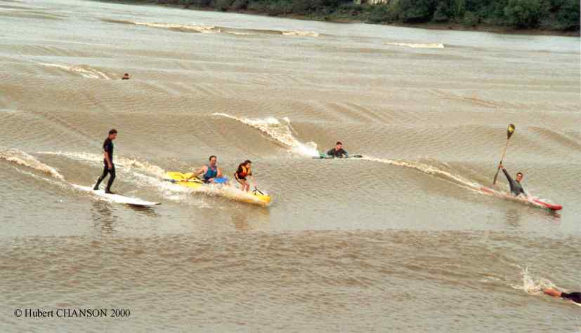
observed the tidal bore of the Dordogne river on 27 Sept. 2000 (5:00pm).
The bore propagates first in the Gironde
before separating and continuing both in the Garonne and in the Dordogne (Map).
At St Pardon, the tidal bore was an undular bore on the 27 Sept. 2000.
Photographs No. 1 and 3 illustrate the undular nature of the positive surge. Photo No. 1
shows the arriving bore. Photo No. 2
illustrates kayacks and surfers riding the bore. Photo No. 3
was taken just downstream of St Pardon while Photo No. 4 was
shot in front of St Pardon.
More pictures of tidal bores are here.More about the tidal bore (mascaret) of the Seine river ...Reference : CHANSON, H. (2001). "Flow Field in a Tidal Bore : a Physical Model." Proc. 29th IAHR Congress, Beijing, China, Theme E, Tsinghua University Press, Beijing, G. LI Ed., pp. 365-373 (ISBN 7-302-04676-X/TV). (CD-ROM, Tsinghua University Press, ISBN 7-900637-10-9.) (download PDF file)
4. Flow resistance in open channel
flows
In open channel flows, flow resistance can be
neglected over a short transition as a first approximation, and the
continuity and Bernoulli equations can be applied to estimate the downstream
flow properties as functions of the upstream flow conditions and boundary
conditions. But the approximation of frictionless flow is no longer valid for
long channels. Considering a water supply canal extending over several
kilometres, the bottom and sidewall friction retards the fluid, and, at
equilibrium, the friction force counterbalances exactly the weight force
component in the flow direction.
The laws of flow
resistance in open channels are essentially the same as those in closed pipes.
In an open channel, the calculations of the boundary shear stress are
complicated
by the existence of the free surface and the wide variety of
possible cross-sectional shapes. The boundary shear stress equals :
to = f/8
* r * V2
where f is the Darcy-Weisbach
friction factor and V is the mean flow velocity (HENDERSON 1966, CHANSON
1999). As for pipe flows, the flow regime in open channels can be either
laminar or turbulent. In industrial applications, it is commonly accepted that
the flow becomes turbulent for Reynolds numbers larger than 2000 to 3000, the
Reynolds number being defined for pipe and open channel flows as Re =
V*DH/n where DH is the hydraulic
diameter or equivalent pipe diameter. The Darcy friction
factor f may be calculated as a function of the relative roughness
ks/DH and Reynolds number from the Moody diagram
In open channels, the Darcy-Weisbach friction equation
(see above) is valid using the hydraulic diameter as equivalent pipe diameter.
It is the only sound method to estimate the energy loss. For various reasons
(mainly historical reasons), empirical resistance coefficients (e.g. Chézy
coefficient) were and are still used. The Chézy coefficient was introduced in
1768 while the Gauckler-Manning coefficient was first presented in 1865 : i.e.,
well before the classical pipe flow resistance experiments in the 1930s.
Historically both the Chézy and the Gauckler-Manning coefficients were expected
to be constant and functions of the roughness only. But it is now well
recognised that these coefficients are only constant for a range of flow rates.
Most friction coefficients (except perhaps the Darcy friction factor) are
estimated 100%-empirically and they apply only to fully-rough turbulent water
flows (CHANSON
1999).
Note : The Gauckler-Manning equation is often called improperly the Manning equation. In fact it was first proposed by the Frenchman P.G. GAUCKLER in 1867 (GAUCKLER 1867) based upon the re-analysis of experimental data obtained by H.P.G. DARCY and H. BAZIN (DARCY and BAZIN 1865). Robert MANNING (1816-1897), chief-engineer at the Office of Public Works, Ireland, presented two flow resitance formula in 1890. One was the 'Gauckler-Manning' formula but Robert MANNING did prefer to use his second formula.
Culvert design
A culvert is a covered channel
of relatively short length designed to pass water through an embankment (e.g.
highway, railroad, dam). It is a hydraulic structure and it may carry flood
waters, drainage flows, natural streams below earthfill and rockfill structures.
From a hydraulic aspect, a dominant feature of a culvert is whether it runs full
or not.
The design can vary from a simple geometry (i.e. box culvert) to
a hydraulically-smooth shape (i.e. MEL culvert, photo No. 1
& photo No.
2). The lectures review first the design of standard culverts, then the design of minimum energy
loss culverts.
Box culvert calculations
Hydraulic calculations of upstream head
above invert bed for box culverts with Inlet Control (Concrete Pipe
Association of Australia 1991) (DOUBLE-CLICK
for full size .WMF file)
Hydraulic calculations of total head losses for
concrete box culverts flowing full (i.e. drowned) (Concrete Pipe
Association of Australia 1991) (DOUBLE-CLICK for
full size .TIF file)
Alternative : .PDF file (both
charts)
More photographs of culverts ...More about the design of Minimum Energy Loss culverts and bridge waterways ...
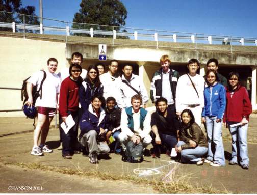 MEL culvert outlet. Field trip in Aug. 2001 with
CIVL3120 class
MEL culvert outlet. Field trip in Aug. 2001 with
CIVL3120 class Open channel hydraulics - Text book exercises with solutions:
http://www.bh.com/companions/0340740671/exercises/ (or http://www.bh.com/companions/0340740671/exercises/exercisesP1.htm).Tutorial No. 1 : Fluid properties and basic equations. Bernoulli principle (1) (version 17/8/02).
Tutorial No. 2 : Bernoulli principle (2). Momentum principle. Hydraulic jump, surges, flow resistance.
Tutorial No. 3 : Uniform equilibrium and gradually-varied flows.
Tutorial No. 4 : Flood plain and backwater calculations (version 1/9/02)
Tutorial No. 5 : Physical modelling. (version 26/8/02)
Tutorial No. 6 : Culvert design. (version 27/8/02)
Revision assignment : Hydraulics of the Nimes aqueduct (version 14/10/02) [1 Mb]
 Tidal bore on the Dordogne river (27/9/2000)
Open channel hydraulicsGeneral information - Experiment description - Time schedule
Laboratory work is closely linked with the lecture program and it is an integral part of the hydraulics course. Four experiments are conducted during the semester.
Two experiments are linked to basic open channel flow. : a study of a broad-crested weir overflow (photo) and the hydraulic jump (photo No. 1, photo No. 2). The former (broad-crested weir) is a smooth transition from an upstream sub-critical flow to a downstream supercritical flow. The latter (hydraulic jump) is the transition from an upstream supercritical flow to a downstream subcritical flow.
The students conduct two further experiments on culvert design (photo) and backwater effects in a long channel (photo No.1, photo No. 2). The main purpose of the frmer experiment is to understand the differences between the hydraulic performances of two different types of culverts carrying the same flow rate (photo No. 1, photo No. 2). (Read about the minimum energy loss culvert.). The purpose of the long channel experiment is to demonstrate open channel control features, and to quantify friction and backwater effects in waterways. In each case, the experimental procedure includes observations, prediction (numerical modelling) and evaluation (comparison between data and computations).
Field trip on Thi. 18 Sept. 2003
Storm waterway system in helenvale, incl. culverts and dissipators
Minimum Energy Loss culverts beneath the South-East freeway : Instructions and outline. (version 13 Aug. 2003)
Field trip on Wed. 11 Sept. 2002
Minimum Energy Loss culverts beneath the Gateway motorway and Gold Creek dam spillway : Instructions and outline. (version 13 Aug. 2002)
Read on the Minimum Energy Loss culverts and History of the Gold Creek dam spillway.Photographs
MEL culvert No. MEL-C-4 (CHANSON 1999). Design discharge : ~220 m3/s. MEL culvert beneath the Gateway motorway (Brisbane, Australia). Photo No. 1a : inlet on 11 Sept. 2002 during CIVL3140 student field trip. Photo No. 1b : inlet wingwall on 11 Sept. 2002 during CIVL3140 student field trip.
MEL culvert No. MEL-C-5 (CHANSON 1999). Design discharge : ~100 m3/s. MEL culvert beneath the Gateway motorway (Brisbane, Australia). Photo No. 2a : inlet on 11 Sept. 2002 during CIVL3140 student field trip. Photo No. 2b : students in inlet channel on 11 Sept. 2002 during CIVL3140 student field trip. Photo No. 2c : students at the dowsntream end of the barrel on 11 Sept. 2002 during CIVL3140 student field trip.
Gold Creek dam spillway on 11 Sept. 2002 : Photo 3a and Photo 3b/
/
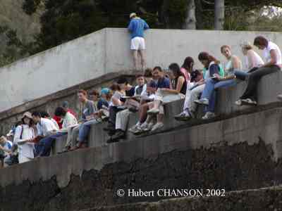
Photographs
Field trip to minimum energy loss waterway (Aug. 2000), (Aug. 2001), (May 2002).
Field trip to Gold Creek dam (Aug. 2000).. Read on the History of the Gold Creek dam spillway.
Rating : [***] = superb, must see - [**] = excellent
Rivers Seen from Space [**]
EPA Multimedia projects (USA) (computations, remote sensing)
Structurae, International Database and Gallery of Structures [**]
Gallery of Photographs in Fluid Mechanics, Hydraulic & Environmental Engineering and Engineering History
Internet resources in Hydraulic & Environmental Engineering
Aerial photographs of American rivers and valleys [**]
NASA Earth observatory [***]
NASA Visible Earth [***]The Formal Water Garden
Unesco World Heritage Listing (for Virtual Tours, click here [**])Unesco Photobank [**]
Gallery of photographs in fluid dynamics by Mark Kramer [**]
SoftwaresHydrochan (TM) [**] Gradually-varied flows (1D) (for teaching purposes ONLY)
US Army Corps of Engineers HEC Softwares
LacusCurtius - Roman Waterworks and Hydraulic Engineering [***]
Roman Aqueducts and Water Systems (Rome aqueduct system)
Ostia - Harbour of Ancient Rome (Italy)
Gorze Aqueduct at Metz (France) [**]
The Aqueduct in Caesarea (Israel)
Aqueduc de Cahors (in French)Hydraulics of Roman Aqueducts : Steep Chutes, Cascades and Dropshafts, AJA, 2000
National Weather Service Office of Hydrology
El Niño Information in California
Extreme reservoir siltation in Australia
River of the World [Map] [**]
The tidal bore of the Seine river
Artifical river habitats and fish passes (photographs)
Flood plains (photographs)
Photographs of River Floods in Australia [**] (Search for : floods)
Aerial photographs of American rivers and valleys [**]
Chicago Calumet waterway: sidestream aeration cascades
Petit-saut dam (French Guyana): aeration cascade
Petit-Saut dam : photographs, dam details
Bureau of Meteorology
Goulburn-Murray Water
Hydro-Electric Corporation (Tasmania)
Murray-Darling Basin Commission
NSW Department of Land and Water Conservation
QLD Department of Natural Resources [Water, Storages] [Glossary of terms]
Mount St. Helens (USA), debris and mud flows, Photofile [**]
California 1997 Flood Images
Chicago Calumet waterway: sidestream aeration cascades
Petit-saut dam (French Guyana)
US Army Corps of Engineers, Walla Walla district [Photographs are listed Here]
US Army Corps of Engineers, Portland district, Photofile [**]History of arch dams
The Rideau Canal (Canada) incl. the 1831 Jones Falls arch dam [*]
Steel damsTimber Crib Weirs in Queensland, Australia
Air entrainment on chutes spillways
Rubber dams
Minimum Energy Loss (MEL) culverts and bridge waterways
Embankment overflow stepped spillways: earth dam spillways with precast concrete blocks
Spillway Aeration Devices to prevent Cavitation Damage in high-head chutes {http://www.uq.edu.au/~e2hchans/aer_dev.html}
ICOLD (International Commission on Large Dams)
Dams Safety Committee of New South Wales Australia
British Dam SocietyBureau of Reclamation Concrete Dams
US Army Corps of Engineers Reservoirs in Pittsburgh's district
US Army Corps of Engineers, Walla Walla district [Photographs are listed Here]
US Army Corps of Engineers, Portland district, Photofile [**]
Gabion hydraulic structures (small dams, weirs) [Maccaferri]
Steel dams
Timber Crib Weirs in Queensland, Australia
History of arch dams
Rubber dams
The Minimum Energy Loss (MEL) weir design
Overflow embankment stepped spillwaysItaipu dam (Brazil/Paraguay)
Petit-saut dam (French Guyana)Spillway design and operation
California 1997 Flood Images
Air entrainment on chutes spillways
Spillway Aeration Devices to prevent Cavitation Damage in high-head chutesStepped spillwaysWorld's oldest stepped spillway (Greece)
Santa Cruz dam stepped spillway (USA)
Greeley spillway (USA) [*]
Stepped spillway photographs
Embankment overflow stepped spillways: earth dam spillways with precast concrete blocks
Hydraulics of Minimum Energy Loss (MEL) culverts and bridge waterways
Introducing Originality and Innovation in Engineering Teaching: the Hydraulic Design of Culverts, European Journal of Engineering Education, Vol. 25, No. 4, pp. 377-391.
Hydraulics of Minimum Energy Culverts and Bridge Waterways, Australian Civil Engrg Trans., I.E.Aust., Vol. CE25, No. 2, pp. 89-95.
SoftwaresHydroculv (TM) [***] Culvert hydraulics (Complete download including VB support files : http://www.compusmart.ab.ca/dwilliam/download.htm) (for teaching purposes ONLY)
Hydrochan (TM) [**] Gradually-varied flows (1-D) (for teaching purposes ONLY)
French Naval and Hydrographic Service SHOM [**]
Tidal bore (mascaret) of the Seine river
Photographs of tidal bores (incl. mascaret, pororoca)
WhirlpoolsTide calculations worldwide (in French)
Coastal engineering web page of Dr Robert A. Dalrymple
Tsunami : Information - PhotographsInlets on-line (USACE) [**]
CHANSON, H. (2001). "Teaching Hydraulic Design in an Australian Undergraduate Civil Engineering Curriculum." Jl of Hyd. Engrg., ASCE, Vol. 127, No. 12, pp. 1002-1008 (ISSN 0733-9429). (Download PDF File)
CHANSON, H. (2000). "Introducing Originality and Innovation in Engineering Teaching: the Hydraulic Design of Culverts." European Journal of Engineering Education, Vol. 25, No. 4, pp. 377-391 (ISSN 0304-3797). (Download PDF File)
CHANSON, H., and JAMES, P. (1998). "Teaching Case Studies in Reservoir Siltation and Catchment Erosion." Intl Jl of Engineering Education, Vol.14, No. 4, pp. 265-275 (ISSN 0949-149X). (Download PDF file) (Alternative PDF file)
University of Queensland LibraryThis page was visited :Measurement systems : SI Units and significant figures
Reprints of Research Papers in Water enginering
ICEnet: The Institution of Civil Engineers Homepage
Japan Society of Civil Engineers
ASCE - American Society of Civil Engineers Homepage
ASME Meetings & Exhibits Frames IndexENPC
Welcome to the IAHR homepageUS Geological Survey
Civil Engineering Resources on the Internet (GuideMe.com)Highlights in the History of Hydraulics by Hunter ROUSE
 times
since 08-12-2000.
times
since 08-12-2000. |
|
|
|
Back to TOP
Back
to Dr Chanson's
Home Page